Overhaul update
Thursday 3rd and 10th March 2018
As readers of these news notes will be aware, a section of the right hand frame from the centre of the middle driving wheel axle box rearwards for about 2 to 3 feet has to be replaced because of a significant crack that showed up when welded repairs (to the left of the hole in the picture) were started as seen in this photo of the inside of the Right hand frame.

The crack disappears behind the flange of the vertical frame stretcher at the top right of the picture. No crack detection sprays required here!

This is the inside of the chassis looking towards the rear with the temporary frame supports and stretchers very much in evidence.

Here you can see the vertical cut made from the top of the RH frame to the top of the middle driving axle box opening.

The RH frame showing just one cut to go at the bottom centre of the picture just below the vertical piece of angle iron clamped to the frame. The forklift truck is being used to support the section of plate being removed.

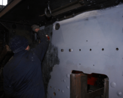
The last cut being carried out by Brian. Note the angle iron has been moved to give Brian a guide for his cutting torch.

Stephen Llewellyn of the paid staff controlling the forklift truck before final removal of the cracked section of plate.

By now the replacement piece of plate has arrived and is seen on a pallet prior to machining and drilling.

The newly created gap in the RH frame - note the “high visibility" white diagonal stripes on the temporary cross member. Also to the right of the gap the chalk sketches show how the remaining frame edges and the edges of the new frame section will be chamfered prior to welding.

The vertical edges of the new plate being chamfered on the big milling machine ready for welding. This work has already been carried out on the existing frames by grinding either side of the new gap as you may be able to see to the right of the previous picture.

The replacement plate on the radial drill ready for drilling various holes using the old plate as a template.

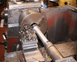
The pony truck pivot bracket has been bushed and a replacement pivot pin turned and fitted. Note the newly machined vertical face - this will require a “shim” of sheet metal between it and the chassis cross member it is fitted to.

